Drawings. Samples. 3D Models.
Or Leave the Design to Us.
Send a drawing, a sample or a 3D CAD file (STEP, IGES, Parasolid, DXF or PDF). Or simply tell us what you need and leave the design to us. We study the application (temperature, media, ingress rating, closure force) and select the compound best suited to it.
Choosing the right compound is the single biggest factor in a long-lasting, failure-proof product. It is what lets a part outlast its maintenance schedule: Fit & Forget.
- Drawing, sample or requirement
- Check the application
- Compare suitable compounds
- Select the formulation
Illustrative sequence · timing is not to scale
Compound Mixing
The selected compound is mixed in a dispersion kneader under high pressure and controlled temperature, dosed to hit the target hardness, tensile strength and elongation, then finished on a two-roll mill into a homogeneous sheet.
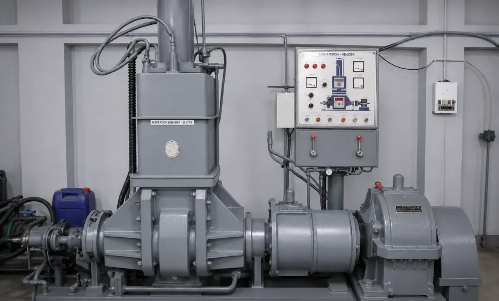
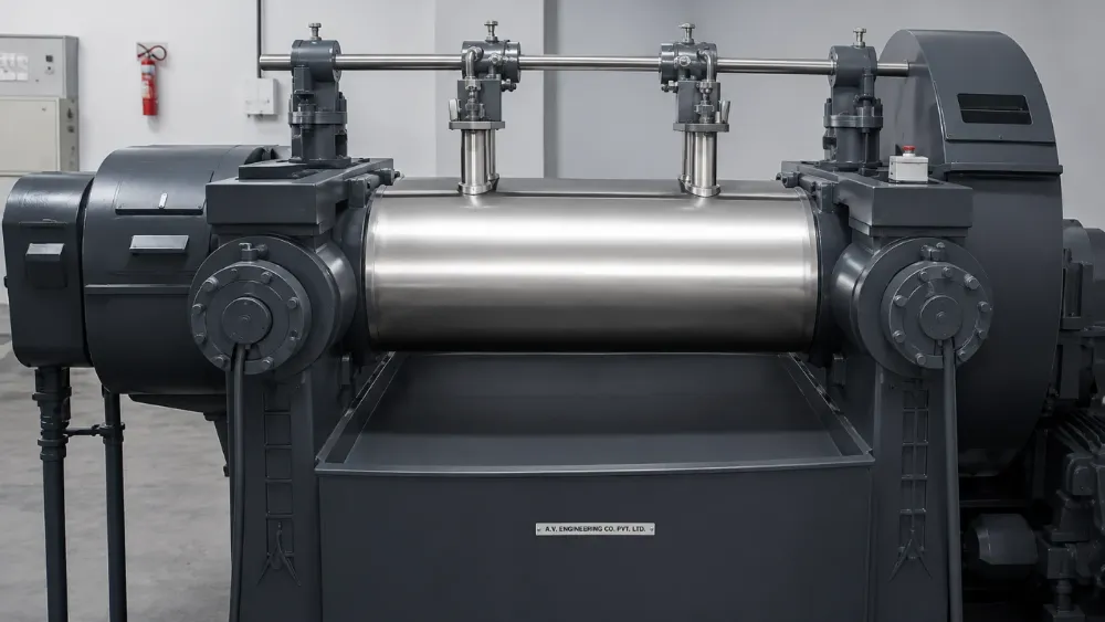
- Mix a batch in the kneader
- Transfer to the two-roll mill
- Add chemicals and form a band
- Take off the finished compound
Illustrative sequence · timing is not to scale
- Test the compound
- Plot the cure response
- Verify specified properties
- Release the tested batch
Illustrative sequence · timing is not to scale
Compound Testing
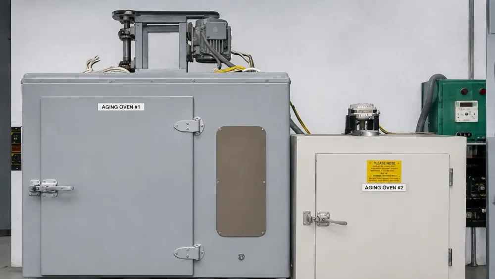
No batch reaches production untested. A rheometer plots the cure curve of every mix; hardness, tensile strength, elongation, density and dispersion are verified against the specification before release.
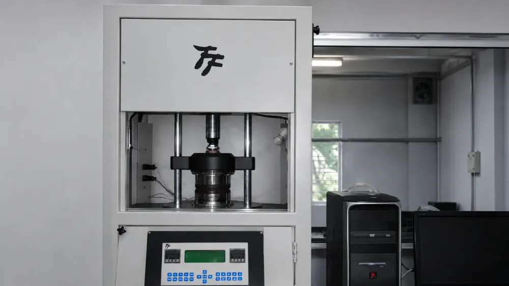
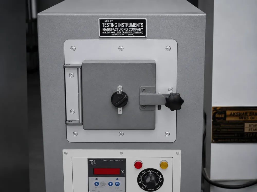
Tooling
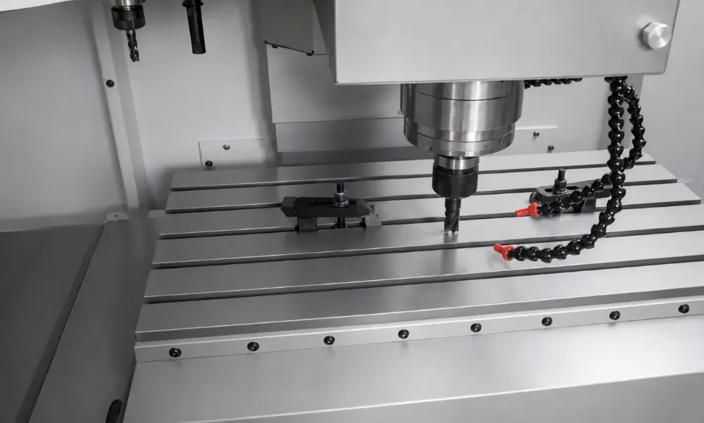
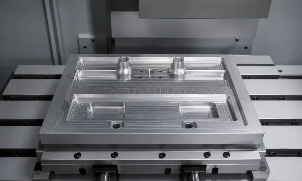
From your drawing, or reverse-engineered from your sample, the component is modelled in 3D CAD. Our CNC toolroom then machines the steel as per the manufacturing process best suited for your component.
- Clamp the steel blank
- Lower the milling cutter
- Cut the cavity and clear chips
- Retract to reveal the tool
Illustrative sequence · timing is not to scale
Two manufacturing routes
The component decides the die. Discrete geometries call for a moulding die, bolted into a hydraulic press. Components that can be extruded and finished downstream get an extrusion die, fitted to the extruder head.
Compression Moulding
The moulding die from the toolroom is bolted into a hydraulic press. Compound blanks cure inside it under heat and pressure. The part is ejected, then flash trimmed.
- Load the compound blank
- Close under heat and pressure
- Hold for curing
- Open and eject the part
Illustrative sequence · timing is not to scale
Extrusion & Joining
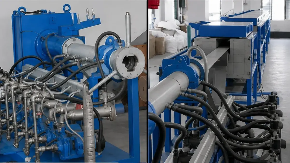
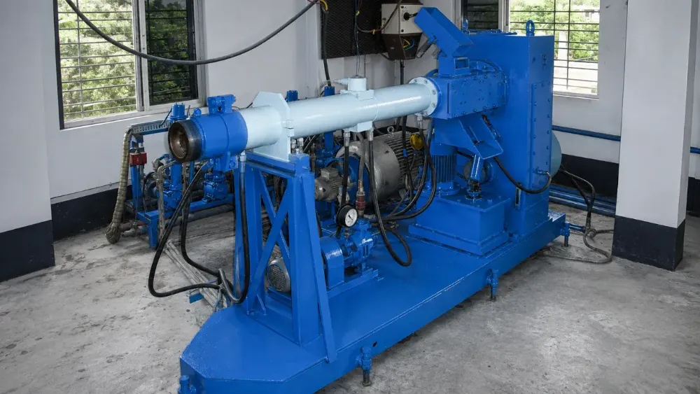
The extrusion die from the toolroom is fitted to the extruder head. The screw conveys compound through it. The shaped profile cures in a 70 ft hot-air vulcanizing oven. Cut lengths are joined end-to-end into jointless, endless gaskets.
- Shape through the extrusion die
- Cure the continuous profile
- Cut to the required length
- Vulcanise the ends into a loop
Illustrative sequence · timing is not to scale
Packing & dispatch
- Prepare the finished parts
- Pack the components
- Close and label the package
- Ready for dispatch
Illustrative sequence · timing is not to scale
All in-house. From compound to component.
Compounding & Mixing
Dispersion kneader plus chilled-roll mixing mills. Every formulation mixed in-house.
In-House Test Laboratory
Moving Die Rheometer, tensile, hardness and abrasion testers, aging ovens.
2 Automated Microwave CV Lines
Dedicated continuous vulcanization lines for EPDM and Silicone.
20+ Hydraulic Moulding Presses
From 10"×10" up to 43"×31" platens, including automatic presses.
Ready when you are.
Send a drawing, sample or spec. Samples turned around extremely quickly.